

 0
0 Mar, 12, 2013
Introduction
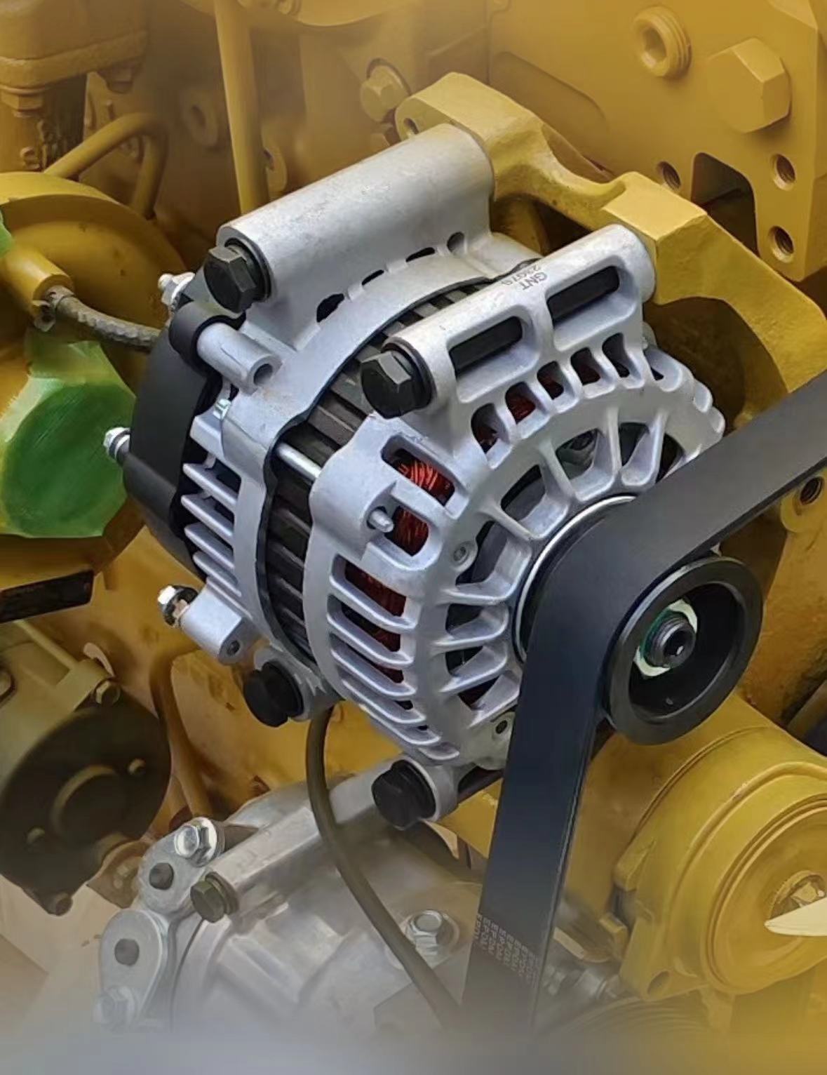
A conventional alternator consists of the following key components: rotor, stator, brush assembly, rectifier, cooling fan, pulley, and front/rear end covers.
Details
Rotor
The rotor generates the rotating magnetic field. Its key components include:
Two claw-pole segments (each with 6 bird-beak shaped poles) press-fitted onto the shaft
Field winding (exciter coil) wound around an iron core within the pole cavity
Two insulated slip rings that transmit DC excitation current to the winding via brushes
When energized, the field winding creates alternating magnetic polarity (N/S poles) between the claw poles, establishing six pairs of magnetic fields.
Stator
The stator assembly produces alternating current and consists of:
Laminated silicon steel core with insulated winding slots
Three-phase stator windings arranged in either:
• Wye (Y) configuration (most common): Phase leads connect to rectifier diodes, neutral ends joined at central point
• Delta (Δ) configuration
Brush Assembly
The brush system comprises:
Two carbon brushes (conduct excitation current)
Brush springs
Brush holder mounted on rear end cover
Rectifier
The diode rectifier converts three-phase AC to DC output:
Six high-current, high-reverse-voltage silicon diodes
Diodes mounted on heat sinks
Configuration:
• Positive diodes (anode terminal)
• Negative diodes (cathode terminal)
End Covers
Front/rear covers feature:
Aluminum alloy construction (non-magnetic, reduced flux leakage)
Lightweight design with superior heat dissipation
Brush holder integrated into rear cover
Ventilation ports for air cooling
Cooling System
The rotating assembly includes:
Drive pulley connected to engine via belt
Axial-flow fan mounted behind pulley
Airflow path:
• Intake through front cover vents
• Exhaust through rear cover vents
• Forced convection cooling during operation